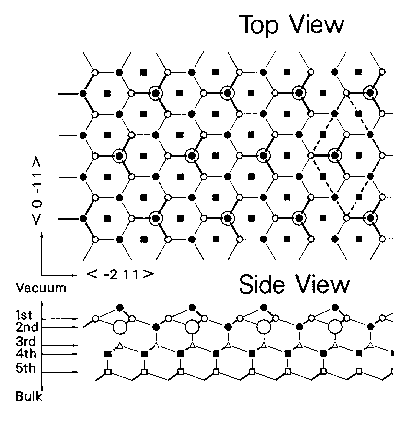
Figure 1.8: The B_5 model for Si{111}rt3xrt3-30-X
The large circles represent substitutional metal (X) atoms in the second layer.
The dashed lines indicated the surface rt3xrt3-30 unit-cell.

 Back to the List of Figures
 Back to the introductory chapter
- Figure 1.1: Schematic of several surface unit-meshes
- Figure 1.2: Schematic of relaxed surface plane
- Figure 1.3: Model of the ideal surface for Si{111}1*1
- Figure 1.4: The Periodic Table of Elements
- Figure 1.5: The T_1 model for Si{111}rt3*rt3-30-X<
- Figure 1.6: The H_3 model for Si{111}rt3*rt3-30-X
- Figure 1.7: The T_4 model for Si{111}rt3*rt3-30-X
- Figure 1.8: The B_5 model for Si{111}rt3*rt3-30-X
- Figure 2.1: Schematic LEED-AES retarding-field analyzer (RFA).


 Back to the introductory chapter